
The Nano ET adapter provides communication between a smartphone or computer and a vehicle. Data exchange between the adapter and the smartphone takes place over WLAN or BLE using the J2534 protocol. Data exchange with the vehicle takes place over the CAN, Ethernet or Kline interfaces, using SAE/ISO automotive protocols.
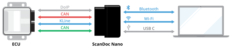
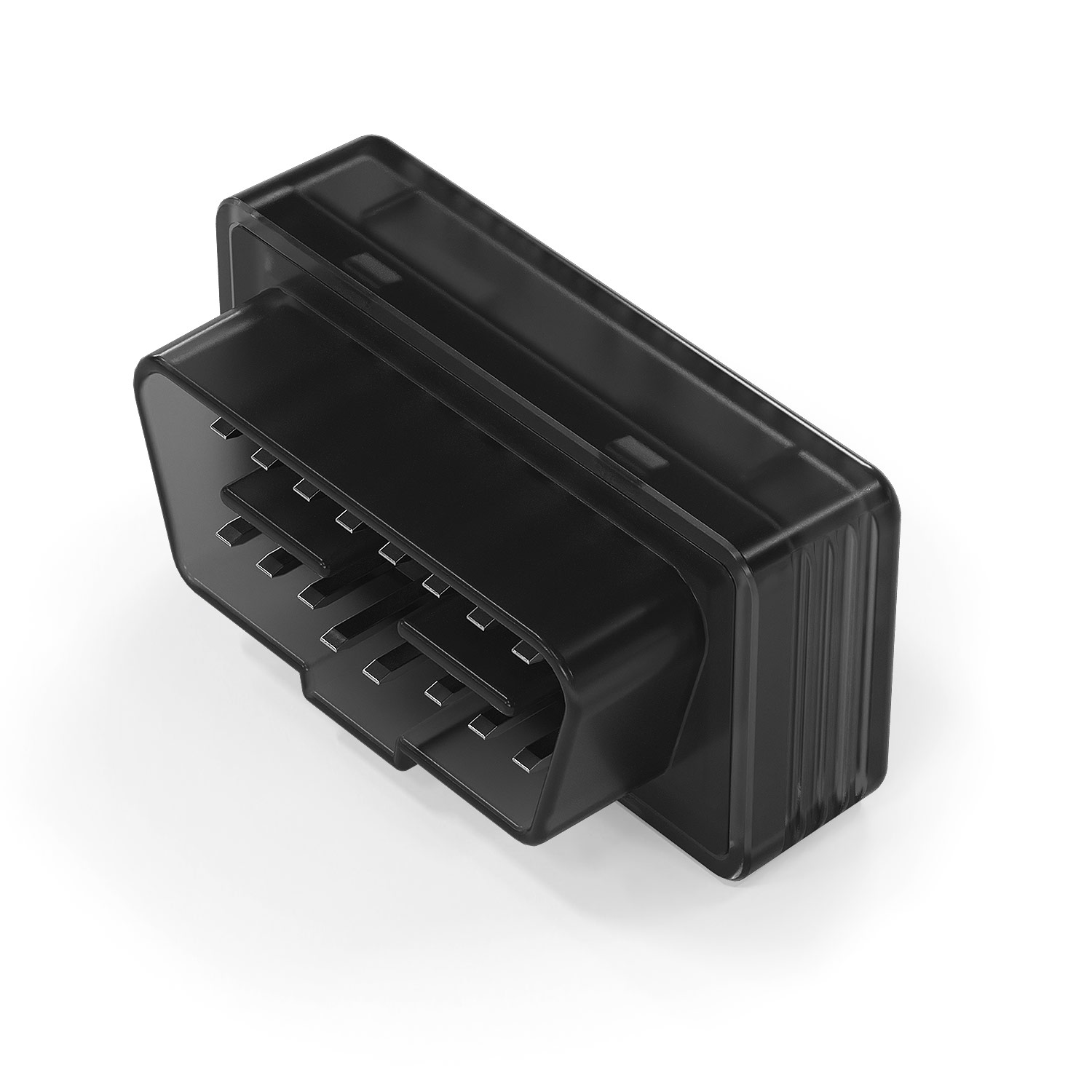
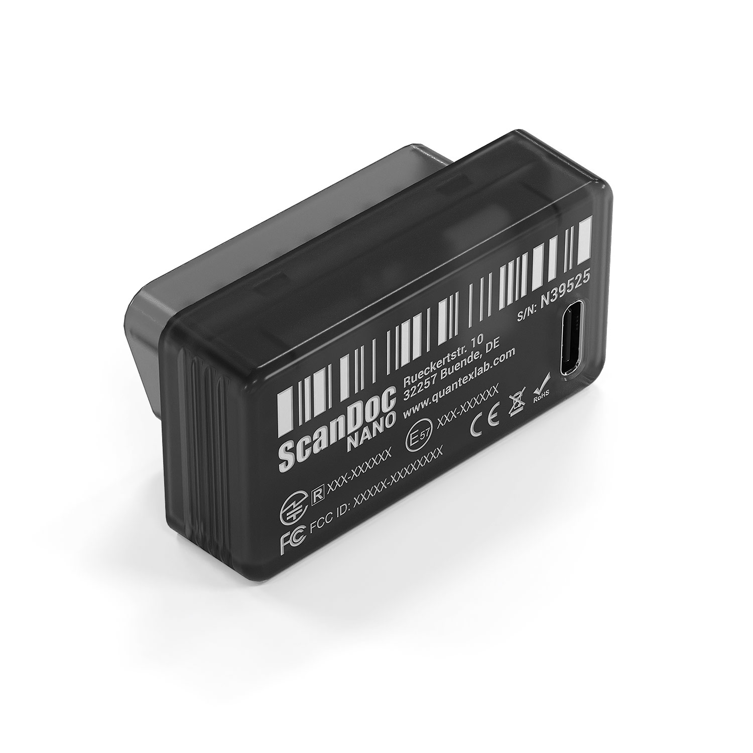
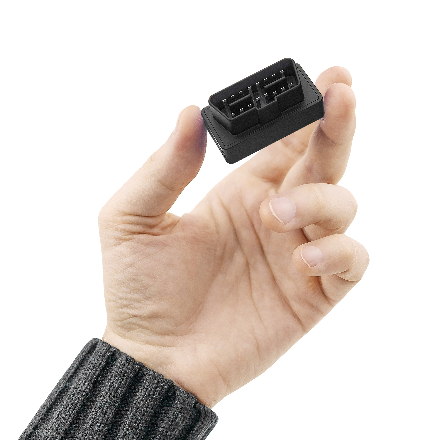
The communication and protocol-processing processor is built on the ESP32-PICO-MINI-02 module.
Module certificates
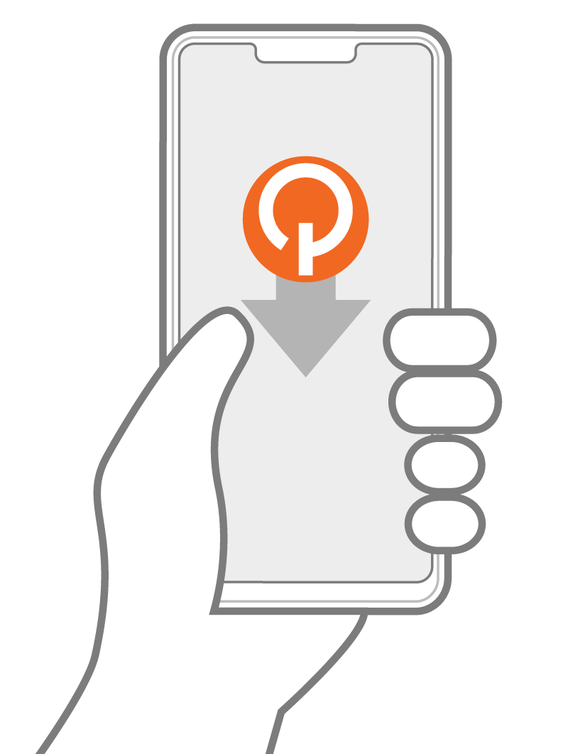
Download and install the application on your smartphone:
QuantexJ2534Demo.apk
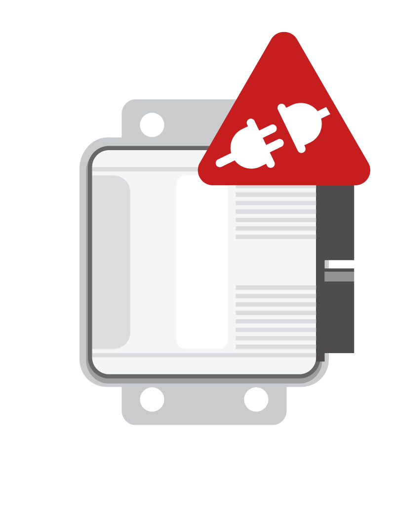
When power is applied, the LED lights up dimly, then brightly, and goes out after the internal tests have completed. The device is then ready for operation.
The device tolerates incorrect power connection. If you use a vehicle control unit for joint testing, keep in mind that the control unit has no reverse-polarity protection. Disconnect the control unit if you need to perform a power stress test.
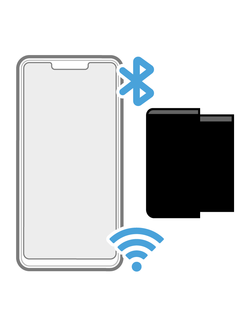
After power is applied, ScanDoc turns on BLE and WLAN at the same time and waits for a smartphone to connect to it. If pairing takes place over BLE, WLAN is disabled, and vice versa. When a smartphone connects to ScanDoc as an access point, it disables the BLE interface. After pairing or connecting over WLAN, the device remembers the choice until power is removed.
If you want to change the connection mode, disconnect the device from power, break the WLAN connection, or delete the stored BLE pairing in the Android settings.
BLE LE - Name:QSNxxxxx, password123456
WLAN - SSID:QSNxxxxx, password:scandocxxxxx
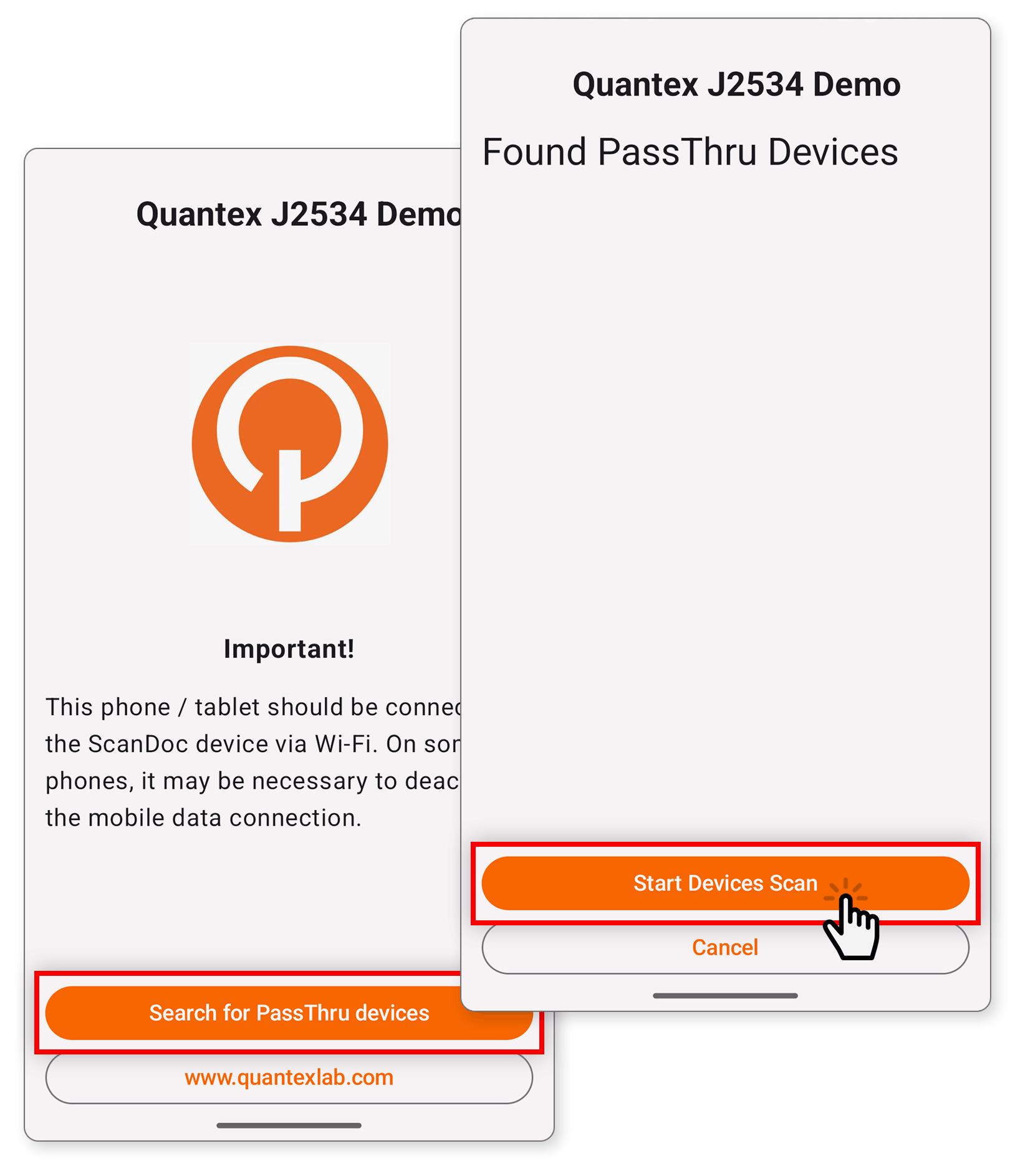
Launch the program on a smartphone running Android up to version 15. Click the "Search for PassThru devices" button, then "Start Devices Scan".
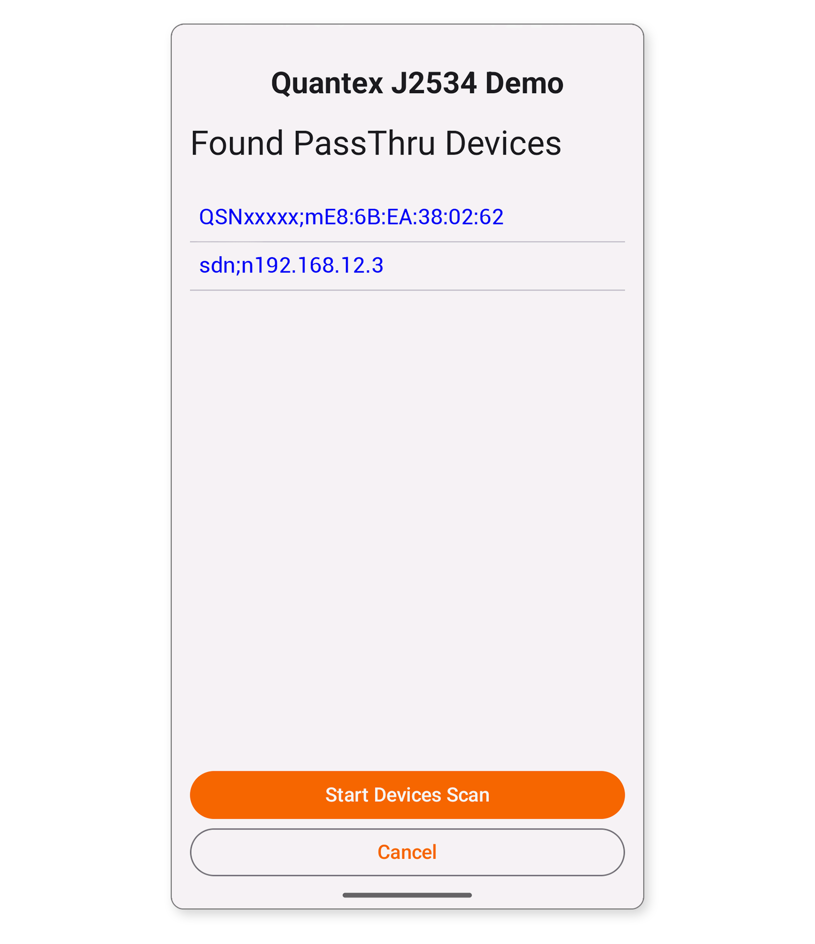
After a short while, a list of discovered devices appears. If you want to connect over WLAN, tap sdn;n:192.168.12.3. If you want to connect over BLE, select QSN;bxx:xx:xx:xx:xx
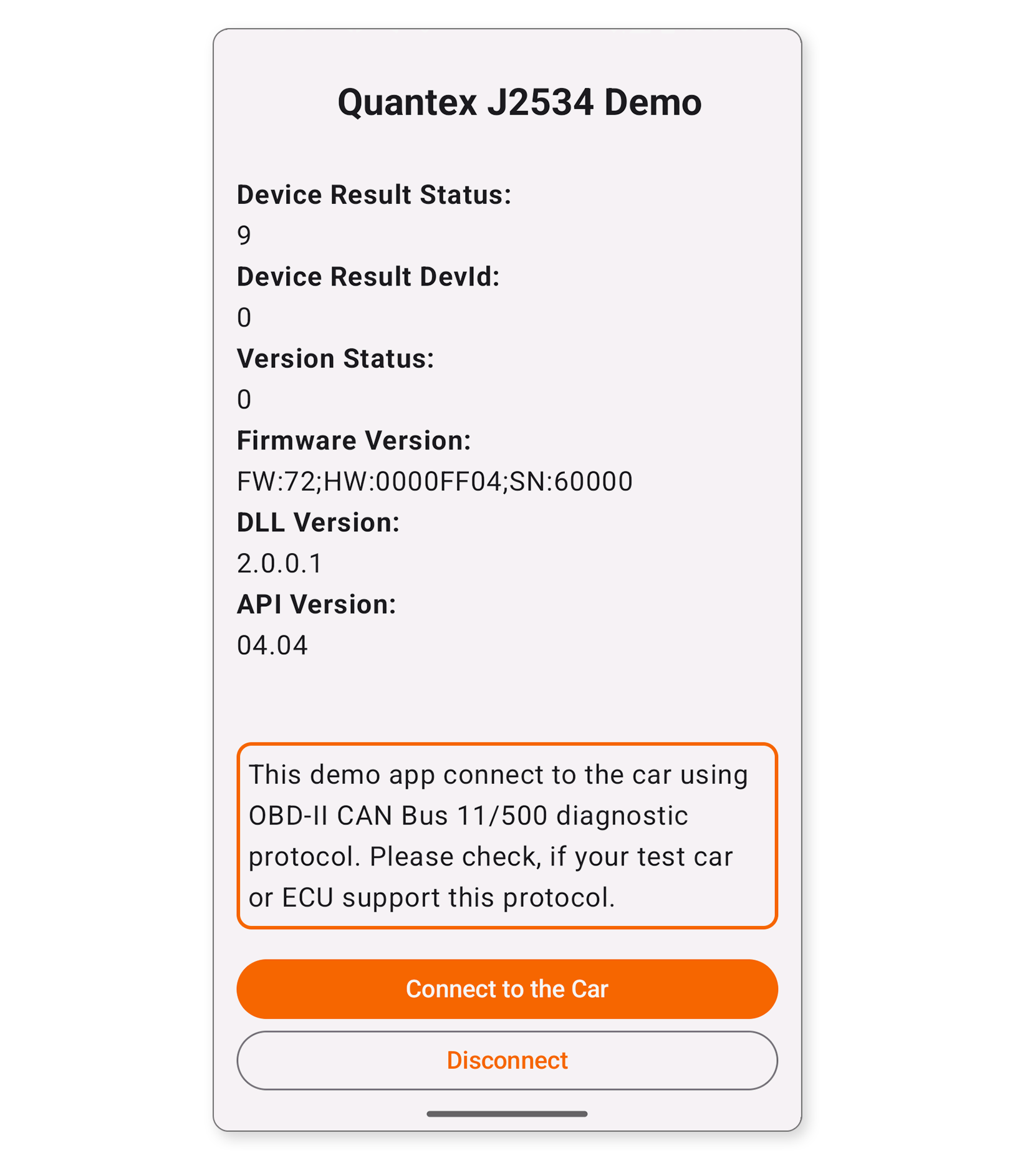
The connection to the adapter is then established and you will see the adapter's Hadrware and Software versions
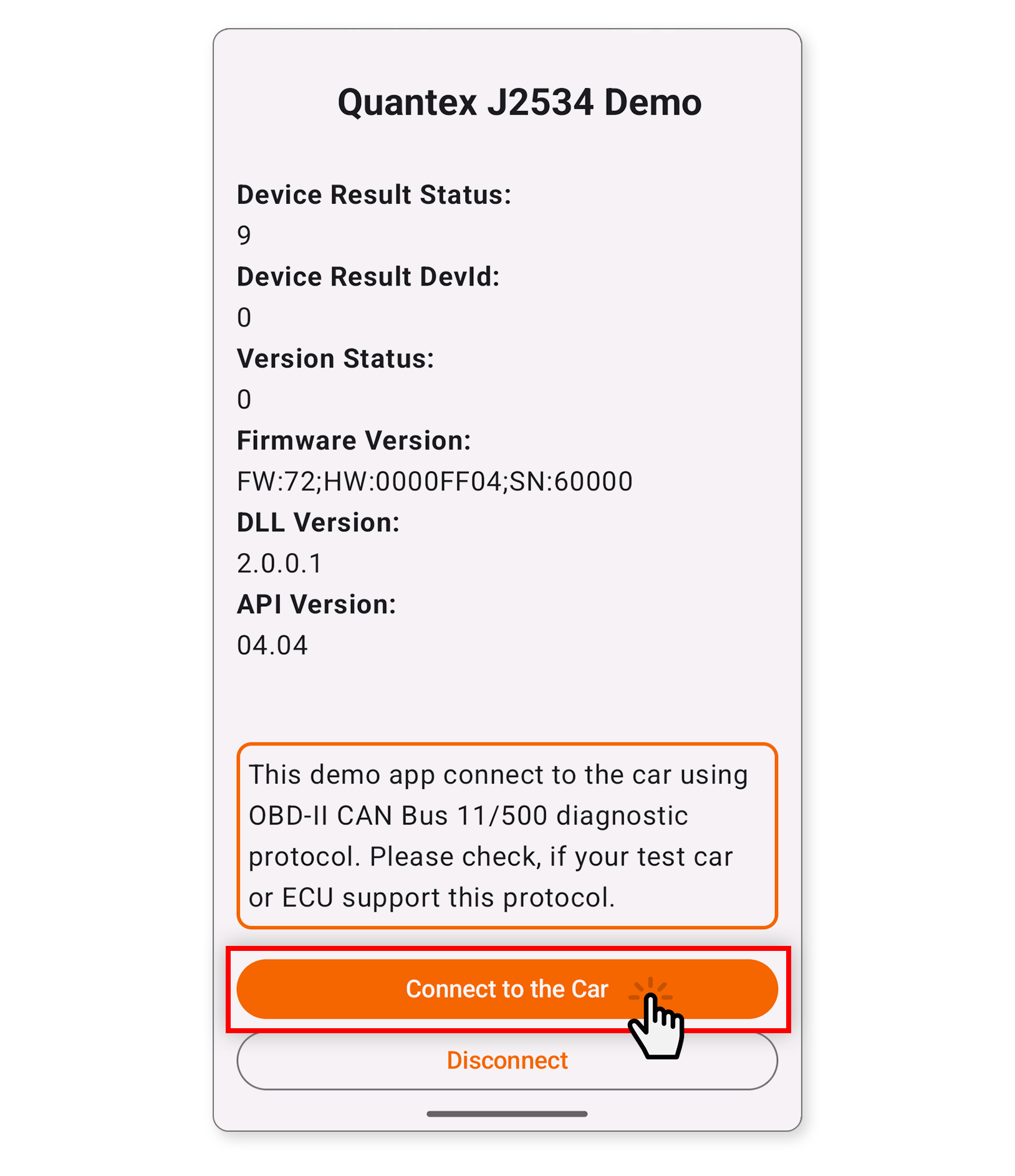
To maintain continuous data exchange, press the "Connect to Car" button. The scanner will begin continuous communication with the vehicle's control unit over the CAN bus. It will also display the supply voltage at pin 16 of the OBD-II connector. At the same time, the LED on the device will light up when a packet is sent and go out when a packet is received.
Download and install the Ping IP network utility application on your smartphone. Or a similar program that can send and receive ping. You can also use a computer.
When power is applied, the LED lights up dimly, then brightly, and goes out after the internal tests have completed. The device is then ready for operation.
The device tolerates incorrect power connection. If you use a vehicle control unit for joint testing, keep in mind that the control unit has no reverse-polarity protection. Disconnect the control unit if you need to perform a power stress test.
In DoIP (Ethernet) mode, ScanDoc works only over a WLAN connection. It creates a bridge between WLAN and Ethernet. Connect to the device over WLAN.
WLAN - SSID:QSNxxxxx, password:scandocxxxxx
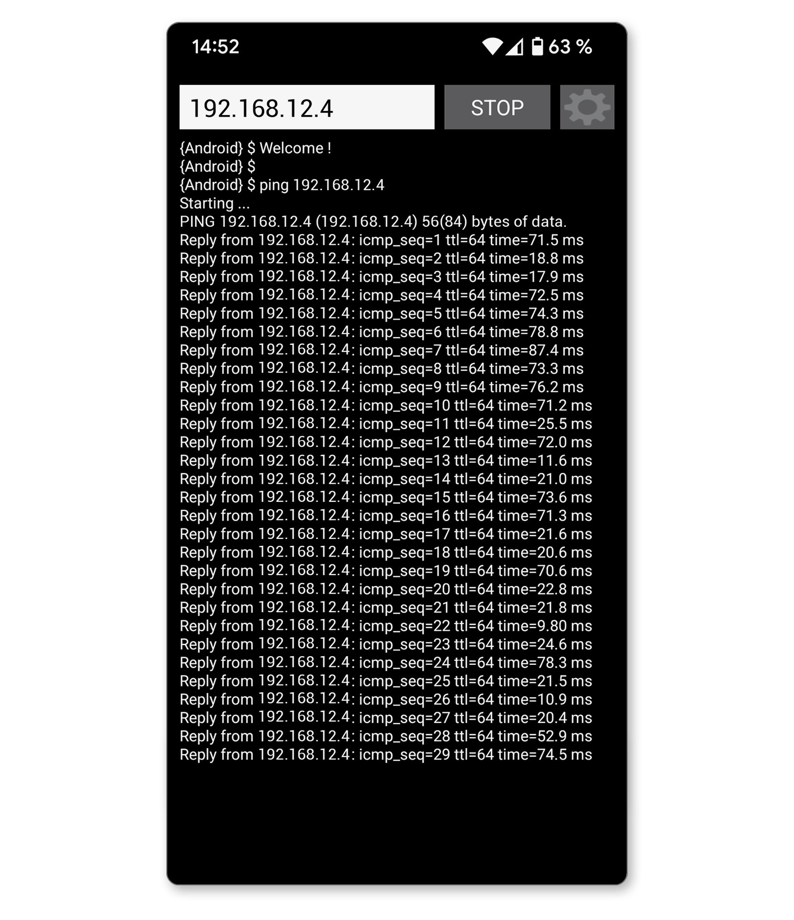
Use the application to send ping commands to the address 192.168.12.4 . The indicator on the device will blink as each packet is transmitted over Ethernet. If there is no blinking, change the address to 192.168.12.5